(Arduino) Servo Control Advanced
- Mar 13
- 2 min read
Updated: Mar 19


Inside a servo
1️⃣ DC motor – spins the gears
2️⃣ Gearbox – slows the motor down and adds torque.
3️⃣ Control circuit – compares input signals to the feedback.
4️⃣ Variable resistor (potentiometer) – tells the servo what angle it’s currently at.

How PWM moves a servo
A servo doesn’t rotate freely — its internal circuit reads a PWM signal: a steady series of repeating pulses.
Each pulse’s length (width) tells the servo what angle to move to.
Pulse every 20 ms → frequency ≈ 50 Hz.
High (ON) time varies:
≈ 1.0 ms → 0 degrees
≈ 1.5 ms → 90 degrees
≈ 2.0 ms → 180 degrees

Purpose of the variable resistor
The variable resistor (potentiometer) is connected to the output shaft — the part that turns.As the servo rotates, the potentiometer’s wiper moves, changing its resistance.
That change in resistance tells the control circuit exactly how far the shaft has turned.
It’s basically a position sensor — a built‑in “angle detector” that turns rotation into a voltage signal.
So:
Different angle → different voltage
That voltage = feedback to the control circuit
Importance of Edge Detection
Edge detection is critical in embedded systems because it distinguishes between a button's state and state changes. Without it, code executes thousands of times per second while a button is held, causing repeated unwanted actions, servo jitter, and wasted resources. Edge detection ensures each button press triggers exactly one action, creating predictable, user-friendly behavior. It's the difference between professional, reliable code and buggy, frustrating interfaces that respond chaotically to user input.
Without edge detection
The loop() runs thousands of times per second
If you hold the button for 1 second, the loop might run 10,000+ times
Each time through the loop, it sees buttonState == LOW
So it triggers the servo movement 10,000+ times while you're holding the button
Your servos would constantly try to move, getting stuck or jittering
Code Snippet:

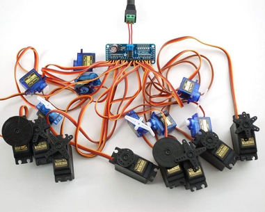
Distinctions between the Servo and the Adafruit PWMServoDriver
The Adafruit PWMServoDriver library controls many servos through an external PCA9685 board using I²C, offloading timing
from the microcontroller.
The standard Servo library directly drives servos from Arduino PWM pins but supports fewer motors and uses CPU timing.
PCA9685 = multi‑servo hardware control;
Servo = simple, direct.


Comments